This is my last article in this blog. I have told about only basic components of electronic circuits and there are a lot of nteresting things in electronic. I hope this mini blog will be useful for students and novice radio amateur.
RELAY
A relay is classified into many types, a standard and generally used relay is made up of electromagnets which in general used as a switch. Dictionary says that relay means the act of passing something from one thing to another, the same meaning can be applied to this device because the signal received from one side of the device controls the switching operation on the other side. So relay is a switch which controls (open and close) circuits electromechanically. The main operation of this device is to make or break contact with the help of a signal without any human involvement in order to switch it ON or OFF. It is mainly used to control a high powered circuit using a low power signal. Generally a DC signal is used to control circuit which is driven by high voltage like controlling AC home appliances with DC signals from microcontrollers.
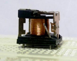
An electromechanical relay is basically designed using few mechanical parts like Electromagnet, a movable armature, contacts, yoke, and a spring/frame/stand, these parts are showing in the internal pictures of Relay below. All these are arranged logically to form into a relay
How relays work
Here are two simple animations illustrating how relays use one circuit to switch on a second circuit.
When power flows through the first circuit (1), it activates the electromagnet (brown), generating a magnetic field (blue) that attracts a contact (red) and activates the second circuit (2). When the power is switched off, a spring pulls the contact back up to its original position, switching the second circuit off again.
This is an example of a «normally open» (NO) relay: the contacts in the second circuit are not connected by default, and switch on only when a current flows through the magnet. Other relays are «normally closed» (NC; the contacts are connected so a current flows through them by default) and switch off only when the magnet is activated, pulling or pushing the contacts apart. Normally open relays are the most common.
Here’s another animation showing how a relay links two circuits together. It’s essentially the same thing drawn in a slightly different way. On the left side, there’s an input circuit powered by a switch or a sensor of some kind. When this circuit is activated, it feeds current to an electromagnet that pulls a metal switch closed and activates the second, output circuit (on the right side). The relatively small current in the input circuit thus activates the larger current in the output circuit:
- The input circuit (blue loop) is switched off and no current flows through it until something (either a sensor or a switch closing) turns it on. The output circuit (red loop) is also switched off.
- When a small current flows in the input circuit, it activates the electromagnet (shown here as a dark blue coil), which produces a magnetic field all around it.
- The energized electromagnet pulls the metal bar in the output circuit toward it, closing the switch and allowing a much bigger current to flow through the output circuit.
- The output circuit operates a high-current appliance such as a lamp or an electric motor.
Inductor

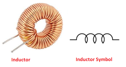
An Inductor is a passive electrical component consisting of a coil of wire which is designed to take advantage of the relationship between magentism and electricity as a result of an electric current passing through the coil.
Inductor allows DC to pass through it while it blocks AC source. It is mostly used in filters for separating the signals of different frequencies.
Batteries


An electric battery is a device consisting of two or more electro-chemical cells that convert stored chemical energy into electrical energy. Each cell has a positive terminal, or cathode, and a negative terminal, or anode. The terminal marked positive is at a higher electrical potential energy than is the terminal marked negative. These are especially handy when it comes to designing portable devices. Now there are many different kinds of batteries such as lead acid or AGM batteries but i wont get into it to much as it doesn’t really change the concept of the battery. All you need to know is that a battery(cell) can store a charge a release it at a later point without deteriorating too much.
You can find these in pretty much any portable device. (laptop, remote, phone, rc toys)
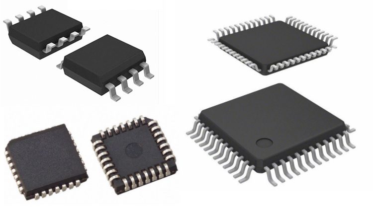
INTEGRATED CIRCUITS
An integrated circuit is a circuit that’s been reduced in size to fit inside a tiny chip. This circuit contains electronic components like resistors and capacitors but on a much smaller scale. Integrated circuits come in different variations such as 555 timers, voltage regulators, microcontrollers and many more. Each pin on an IC is unique in terms of it’s function.
Before you design an electronic project, you need to know what a circuit is and how to create one properly.
An electronic circuit is a circular path of conductors by which electric current can flow. A closed circuit is like a circle because it starts and ends at the same point forming a complete loop. Furthermore, a closed circuit allows electricity to flow from the (+) power to the (-) ground uninterrupted.
In contrast, if there is any break in the flow of electricity, this is known as an open circuit. As shown below, a switch in a circuit can cause it to be open or closed depending on it’s position.

All circuits need to have three basic elements. These elements are a voltage source, conductive path and a load.
The voltage source, such as a battery, is needed in order to cause the current to flow through the circuit. In addition, there needs to be a conductive path that provides a route for the electricity to flow. Finally, a proper circuit needs a load that consumes the power. The load in the above circuit is the light bulb.
Transistors
Transistor, the invention that changed the future of electronic circuits. It is a semiconductor device that can be used to either switch electrical power or amplify electronic signals.
A Transistor is a 3 terminal device that can be either a current controlled device or a voltage controlled device.Different types of transistors exists.Basically they are classified as
1) Bipolar Junction Transistors (BJT) and
2) Field Effect Transistors (FET).
They can be further classified as shown below
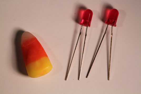
LED (The Light Emitting Diodes)
Light Emitting Diodes or simply LED´s, are among the most widely used of all the different types of semiconductor diodes available today and are commonly used in TV’s and colour displays.

They are the most visible type of diode, that emit a fairly narrow bandwidth of either visible light at different coloured wavelengths, invisible infra-red light for remote controls or laser type light when a forward current is passed through them.
The “Light Emitting Diode” or LED as it is more commonly called, is basically just a specialised type of diode as they have very similar electrical characteristics to a PN junction diode. This means that an LED will pass current in its forward direction but block the flow of current in the reverse direction.
Light emitting diodes are made from a very thin layer of fairly heavily doped semiconductor material and depending on the semiconductor material used and the amount of doping, when forward biased an LED will emit a coloured light at a particular spectral wavelength.
When the diode is forward biased, electrons from the semiconductors conduction band recombine with holes from the valence band releasing sufficient energy to produce photons which emit a monochromatic (single colour) of light. Because of this thin layer a reasonable number of these photons can leave the junction and radiate away producing a coloured light output.

LED Construction
Then we can say that when operated in a forward biased direction Light Emitting Diodes are semiconductor devices that convert electrical energy into light energy.
DIODES
A diode is a semiconductor device that essentially acts as a one-way switch for current. It allows current to flow easily in one direction, but severely restricts current from flowing in the opposite direction.
Diodes are also known as rectifiers because they change alternating current (ac) into pulsating direct current (dc). Diodes are rated according to their type, voltage, and current capacity.
Diodes have polarity, determined by an anode (positive lead) and cathode (negative lead). Most diodes allow current to flow only when positive voltage is applied to the anode. A variety of diode configurations are displayed in this graphic:

The schematic symbol for a diode looks like this:

CAPASISTORS
Capacitor is an electronic component that stores electric charge. The capacitor is made of 2 close conductors (usually plates) that are separated by a dielectric material.
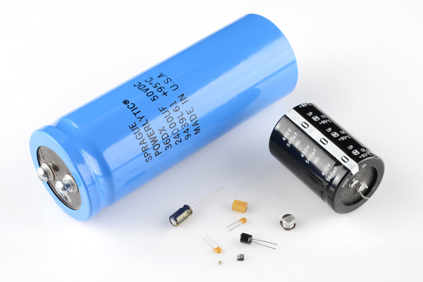
The plates accumulate electric charge when connected to power source. One plate accumulates positive charge and the other plate accumulates negative charge.The capacitance is the amount of electric charge that is stored in the capacitor at voltage of 1 Volt.The capacitor disconnects current in direct current (DC) circuits and short circuit in alternating current (AC) circuits.The capacitance is measured in units of Farad (F).
There are two common ways to draw a capasistor in a schematic:

Resistor
A resisor is a component that resists the flow of current. It’s one of the most basic components used in electronic circuits. If you put resistors next to a penny, you get an idea of how small they are.
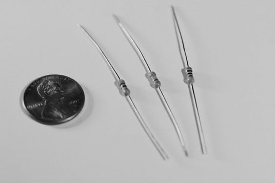
Resistors come in a variety of resistance values (how much they resist current, measured in units called ohms and designated by the symbol Ω and power ratings (how much power they can handle without burning up, measured in watts). Resistors are used for many purposes. A few examples include delimit electric current, voltage division, heat generation, matching and loading circuits, control gain, and fix time constants. They are commercially available with resistance values over a range of more than nine orders of magnitude. They can be used to as electric brakes to dissipate kinetic energy from trains, or be smaller than a square millimeter for electronics. The schematic symbol of the resistor are drawn in two different ways. The american style resistor is drawn as a zigzag resistor while the european style resistor is drawn as a rectangular resistor.